
🔧 Component Breakdown
Example Specifications:
- Type: Welded Diaphragm Bellows
- Material: AISI 316L / AM350
- Diaphragm Pairs: 20
- Wave Shape: S-Curve
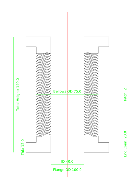
01. Flange:
Customized shape; edge preset with groove. Recommended to use same material as bellows for optimal welding integrity.
02. Bellows:
Stamped metal circular corrugated shape. Thickness and profile are precisely tailored to pressure requirements and cycle life.
03. Pitch:
The distance between adjacent convolutions. This critical dimension affects pressure resistance, durability, and spring rate.
*OD: Outer Diameter, ID: Inner Diameter, D: Effective Diameter
⚙️ Welding & Manufacturing
- Electron Beam Welding (EBW)
- GTAW / TIG & Laser Welding
- Plasma Arc Welding (PAW)
- Cleanroom (Class 100-10,000)
📊 Testing & Reliability
- MST Leak Detection (1×10⁻¹⁰)
- Life Cycle & Pressure Validation
- Metallurgy & Microstructure
- FEA Stress & Fatigue Simulation
✅ Key Characteristics
- > 1 Million Cycles life
- Cryogenic to High-Temp
- Ultra-low outgassing
- High corrosion resistance
Manufacturing Process
Bellows Fabrication
- 🔹 Stamping: Precision plate forming
- 🔹 Diaphragm Cleaning: Ultrasonic/Chemical wash
- 🔹 Vacuum Drying: Moisture removal
- 🔹 Inside Diameter (ID) Welding: Diaphragm pairs
- 🔹 Outside Diameter (OD) Welding: Convolutions
Flange & Components
- 🔸 Raw Material Cutting: Base stock preparation
- 🔸 CNC Lathe: Precision turning
- 🔸 Machining Center: Multi-axis milling
Quality Assurance
Final QC Check
Ready for Shipping
Order Process
Inquiry & Technical Consultation
We welcome all inquiries and look forward to discussing your specific requirements. The goal of our initial communication is to define all technical parameters clearly. Whether you have complete specifications or just a general concept, our team will work closely with you to finalize the design before any production begins.
Step 01: Defining Technical Specifications
For standard or customized products, we typically confirm the following data points to ensure optimal performance:
- Dimensions: Inner Diameter (ID), Outer Diameter (OD).
- Length: Free length, Extension length, and Compression length.
- Vacuum Environment: Is the vacuum applied internally or externally?
- Installation: Vertical or Horizontal placement?
- Internal Setup: Any internal shafts, components, or axial/lateral displacements?
- Drawings/Samples: We are happy to work from your 3D/2D drawings or physical samples if available, but these are not mandatory for our initial discussion.
Step 02: Design Verification & Confirmation
Based on the confirmed data, we will generate a formal engineering drawing for your final review. This ensures the component meets your exact operational needs. This technical design and drawing service is provided free of charge to all our customers.
Step 03: PO Confirmation
Order is finalized based on the approved technical drawing.
Step 04: Production
Manufacturing follows strict stamping, welding, and testing protocols.
Step 05: QC & Delivery
Final inspection and vacuum packaging prior to global shipping.