
In mid-August 2026, Fortune Business Insights projected the global ion implanter market to grow from $3.10 billion in 2026 to $6.97 billion by 2034, a 12.27% CAGR — the fastest-growing segment of the doping equipment market, pulled by advanced-node logic, memory, power semiconductors and specialty devices. The equipment makers agree: Axcelis Technologies reported Q2 2026 revenue of $215.18 million in August, and Applied Materials forecast fourth-quarter revenue above expectations as AI-chip demand drives equipment spending. Every one of those dollars buys a machine that is, in essence, a vacuum beamline.
Ion implantation is how a chip’s electrical personality is written: it fires ionized dopant atoms — boron, phosphorus, arsenic — into silicon at precise depths and doses. The implant must be clean, controlled and repeatable to a degree that only vacuum physics allows. Here is what is inside the box, and why the vacuum hardware matters as much as the beam itself.
Anatomy of an Ion Implanter
Ion source and extraction
The machine starts in an ion source, where dopant gases are ionized in a plasma and extracted into a beam. Source life is measured in hours to weeks — filament and source parts are consumables — so the source chamber is designed for rapid access and exchange, with vacuum isolation valves and bellows-sealed access doors that let operators swap sources without venting the whole beamline.
Mass analysis and beamline
The extracted beam contains unwanted species; a magnetic analyzer bends it so only the correct dopant mass passes through a resolving aperture. The beam then travels down an evacuated beamline, typically at 10-5 to 10-7 mbar, through focusing magnets, acceleration/deceleration electrodes and scanning systems. Beamline components live under constant heat load from beam interception — apertures, slits and faraday cups must be cooled — and every electrostatic element needs high-voltage feedthroughs carrying 10–100 kV into the vacuum envelope, like the high voltage feedthroughs we manufacture.
End station and wafer handling
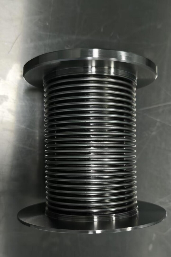
At the end station, wafers are mechanically scanned through the beam — or the beam is scanned across a stationary wafer. The scanning mechanics, wafer transfer robots and clamping stages all operate in vacuum or in load-locked transfer, using bellows like those in wafer handling robots to seal moving shafts and stages. Dose control reads beam current on faraday cups; any drift in vacuum quality shifts the beam and the dose.
Why Vacuum Quality Is a Yield Issue
In an implanter, vacuum is not just cleanliness — it is metrology. Residual gas molecules in the beamline scatter ions out of the beam and neutralize them, changing the delivered dose and energy. A beamline that leaks or outgasses drifts out of calibration; a fab that recalibrates its implanters constantly is a fab losing productivity. That is why implant tools are specified and serviced with the same leak-tight discipline we describe in our helium leak testing guide, and why bellows, valves and seals in the beamline are treated as precision components rather than plumbing.
What the Market Growth Means for Hardware
The 12.27% CAGR is not just more of the same tools. It is driven by shifts that change the hardware mix inside each tool:
- High-dose and high-energy implants for advanced logic and memory raise beam currents and voltages, increasing thermal load on beamline components and the need for robust bellows and feedthroughs.
- Power semiconductors — the SiC and GaN boom we covered in SiC’s 200mm transition and power GaN manufacturing — add implant steps for device termination and body regions, often on new 200mm lines.
- AI-driven fab capacity means more tools per fab and tighter uptime targets; consumables like source parts, bellows and seals must survive longer and swap faster.
- Specialty and quantum-era devices add low-dose, high-precision implants that push vacuum stability requirements further.
Component demand tracks tool shipments with a multiplier: each implanter contains dozens of bellows (beamline, valves, scanning stages, wafer handling), dozens of feedthroughs (HV, RF, thermocouple, motion), and a permanent service stream of replacements. Implanter OEMs and their service networks are, quietly, one of the steadiest consumers of precision vacuum hardware in the fab.
Component Selection Priorities
- High-voltage feedthroughs — beamline electrodes run at 10–100 kV; insulation, creepage and corona-free design matter, as in our 30 kV feedthrough product line.
- Cycle-rated bellows — scanning stages and isolation valves flex millions of times; fatigue life must be documented, per our design guide.
- UHV sealing — beamline integrity at 10-7 mbar demands all-metal joints and leak rates below 1×10⁻⁹ mbar·L/s.
- Thermal management — beam-intercepting parts need cooling paths and materials that hold tolerance at temperature.
The Alpha Technology Angle
Alpha Technology supplies custom edge welded bellows, vacuum feedthroughs (including high-voltage designs) and bellows-sealed assemblies to ion implant tool OEMs and fab service teams — helium-leak-tested, cycle-documented and rated for beamline service. Qualifying components for implant tools? Contact our engineering team with your voltage, motion and vacuum requirements.
FAQ
What does an ion implanter do?
It fires ionized dopant atoms — boron, phosphorus, arsenic — into silicon at controlled energies and doses to dope transistor regions. Implant is one of the most repeated process steps in chipmaking.
Why is ion implantation a vacuum process?
The ion beam must travel from source to wafer without hitting gas molecules, which would scatter and neutralize ions and ruin dose accuracy. Beamlines operate at 10-5 to 10-7 mbar.
How big is the ion implanter market?
Fortune Business Insights projects growth from $3.10 billion in 2026 to $6.97 billion by 2034 at a 12.27% CAGR, driven by advanced nodes, AI capacity and power semiconductors.
What vacuum components are inside an ion implanter?
Ion sources with isolation valves, mass-analysis beamlines, high-voltage feedthroughs for electrostatic optics, scanning-stage bellows, faraday cups and load-lock wafer handling — dozens of bellows and feedthroughs per tool.
Qualifying or servicing ion implant tools? Contact Alpha Technology for leak-tested bellows, high-voltage feedthroughs and valve assemblies.